NCT210
http://onsemi.com
3
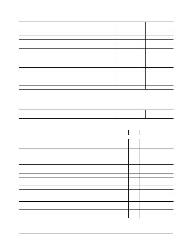
Table 2. ABSOLUTE MAXIMUM RATINGS
Parameter
Rating
Unit
Positive Supply Voltage (V
DD
) to GND
0.3 to +6.0
V
D+, ADD0, ADD1
0.3 to V
DD
+0.3
V
D to GND
0.3 to +0.6
SCLK, SDATA, ALERT
, STBY
0.3 to +6.0
V
Input Current
?0
mA
Input Current, D
?
mA
ESD Rating, All Pins (Human Body Model)
2,000
V
Continuous Power Dissipation
Up to 70癈
Derating Above 70癈
650
6.7
mW
mW/癈
Operating Temperature Range
55 to +125
癈
Maximum Junction Temperature (T
J
MAX
)
150
癈
Storage Temperature Range
65 to +150
癈
Lead Temperature, Soldering (10 sec)
300
癈
IR Reflow Peak Temperature
220
癈
Stresses exceeding Maximum Ratings may damage the device. Maximum Ratings are stress ratings only. Functional operation above the
Recommended Operating Conditions is not implied. Extended exposure to stresses above the Recommended Operating Conditions may affect
device reliability.
NOTE: This device is ESD sensitive. Use standard ESD precautions when handling.
Table 3. THERMAL CHARACTERISTICS
Package Type
q
JA
Unit
16-lead QSOP Package
105
癈/W
Table 4. ELECTRICAL CHARACTERISTICS
(T
A
= T
MIN
to T
MAX
, V
DD
= 3.0 V to 3.6 V, unless otherwise noted) (Note 1)
Parameter
Test Conditions/Comments
Min
Typ
Max
Unit
Power Supply and ADC
Temperature Resolution
Guaranteed No Missed Codes
1.0
癈
Temperature Error, Local Sensor
3.0
?.0
+3.0
癈
Temperature Error, Remote Sensor
T
A
= 60癈 to 100癈
3.0
5.0
+3.0
+5.0
癈
Supply Voltage Range (Note 2)
3.0
3.6
V
Undervoltage Lockout Threshold
V
DD
Input, Disables ADC, Rising Edge
2.5
2.7
2.95
V
Undervoltage Lockout Hysteresis
25
mV
Power-on Reset Threshold
V
DD
, Falling Edge (Note 3)
0.885
1.7
2.2
V
POR Threshold Hysteresis
50
mV
Standby Supply Current
V
DD
= 3.3 V, No SMBus Activity
SCLK at 10 kHz
1.0
4.0
5.0
mA
Average Operating Supply Current
0.25 Conversions/Sec Rate
130
200
mA
Auto-convert Mode, Averaged Over 4 Sec
2 Conversions/Sec Rate
225
370
mA
Conversion Time
From Stop Bit to Conversion Complete
(Both Channels) D+ Forced to D + 0.65 V
65
115
170
ms
Remote Sensor Source Current
High Level (Note 3)
Low Level (Note 3)
120
7.0
205
12
300
16
mA
D Source Voltage
0.7
V
Address Pin Bias Current (ADD0, ADD1)
Momentary at Power-on Reset
50
mA
发布紧急采购,3分钟左右您将得到回复。
相关PDF资料
NCT214MT3R2G
IC TEMP SENSOR LOC/REM 10WDFN
NCT72CMNR2G
IC REMOTE THERMAL SENSOR 8-DFN
NCT7491RQR2G
IC REMOTE THERMAL MONITOR 24QSOP
NCT75MNR2G
IC SENSOR TEMP DGTL 8DFN
NCV8881PWR2G
IC REG TRPL BUCK/LINEAR 16SOIC
NE1617ADS,112
IC TEMP MONITOR 16SSOP
NE1619DS,118
IC TEMP MONITOR 16SSOP
NIS5112D1R2G
IC ELECTRONIC FUSE HOTSWAP 8SOIC
相关代理商/技术参数
NCT214MT3R2G
功能描述:板上安装温度传感器 TEMP SENS W MULTIPLE ADD RoHS:否 制造商:Omron Electronics 输出类型:Digital 配置: 准确性:+/- 1.5 C, +/- 3 C 温度阈值: 数字输出 - 总线接口:2-Wire, I2C, SMBus 电源电压-最大:5.5 V 电源电压-最小:4.5 V 最大工作温度:+ 50 C 最小工作温度:0 C 关闭: 安装风格: 封装 / 箱体: 设备功能:Temperature and Humidity Sensor
NCT218FCT2G
制造商:ON Semiconductor 功能描述:NCT218 CSP OPN - Tape and Reel 制造商:ON Semiconductor 功能描述:REEL / NCT218 CSP OPN 制造商:ON Semiconductor 功能描述:BATTERY PWR
NCT218MTR2G
制造商:ON Semiconductor 功能描述:LOW VOLTAGE LOCAL TEMPERA - Tape and Reel 制造商:ON Semiconductor 功能描述:REEL / LOW VOLTAGE LOCAL TEMPERA 制造商:ON Semiconductor 功能描述:Low Voltage, High Accuracy Temperature Monitor with I2C Interface
NCT22/D
制造商:未知厂家 制造商全称:未知厂家 功能描述:Low Cost Single Trip Point Temperature Sensor
NCT22DR2
制造商:Rochester Electronics LLC 功能描述:- Bulk 制造商:ON Semiconductor 功能描述:
NCT24DR2
制造商:Rochester Electronics LLC 功能描述:- Bulk
NCT2DC12V
制造商:DBLECTRO 制造商全称:DB Lectro Inc 功能描述:Suitable for automobile, automation system,electronicequipment
NCT3012S TR
制造商:Nuvoton Technology Corp 功能描述:ADVANCED POWER CONTROL IC 制造商:Nuvoton Technology Corp 功能描述:IC PWR SAVING CTLR
